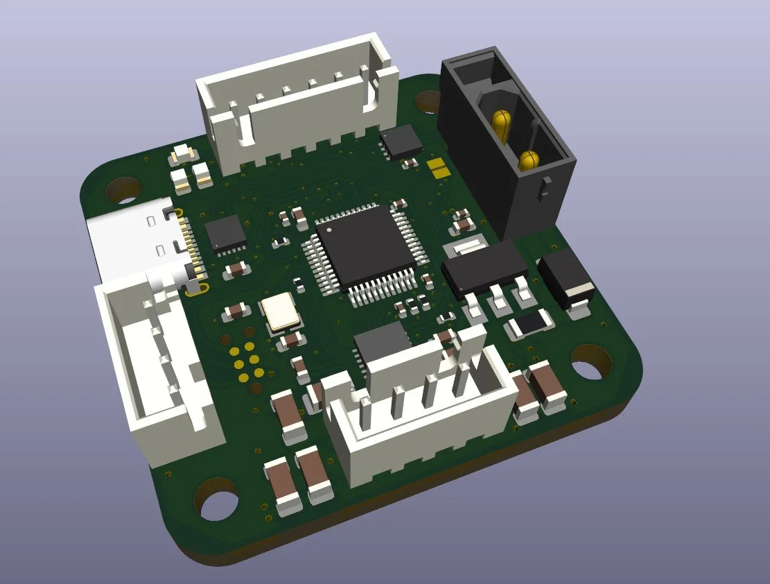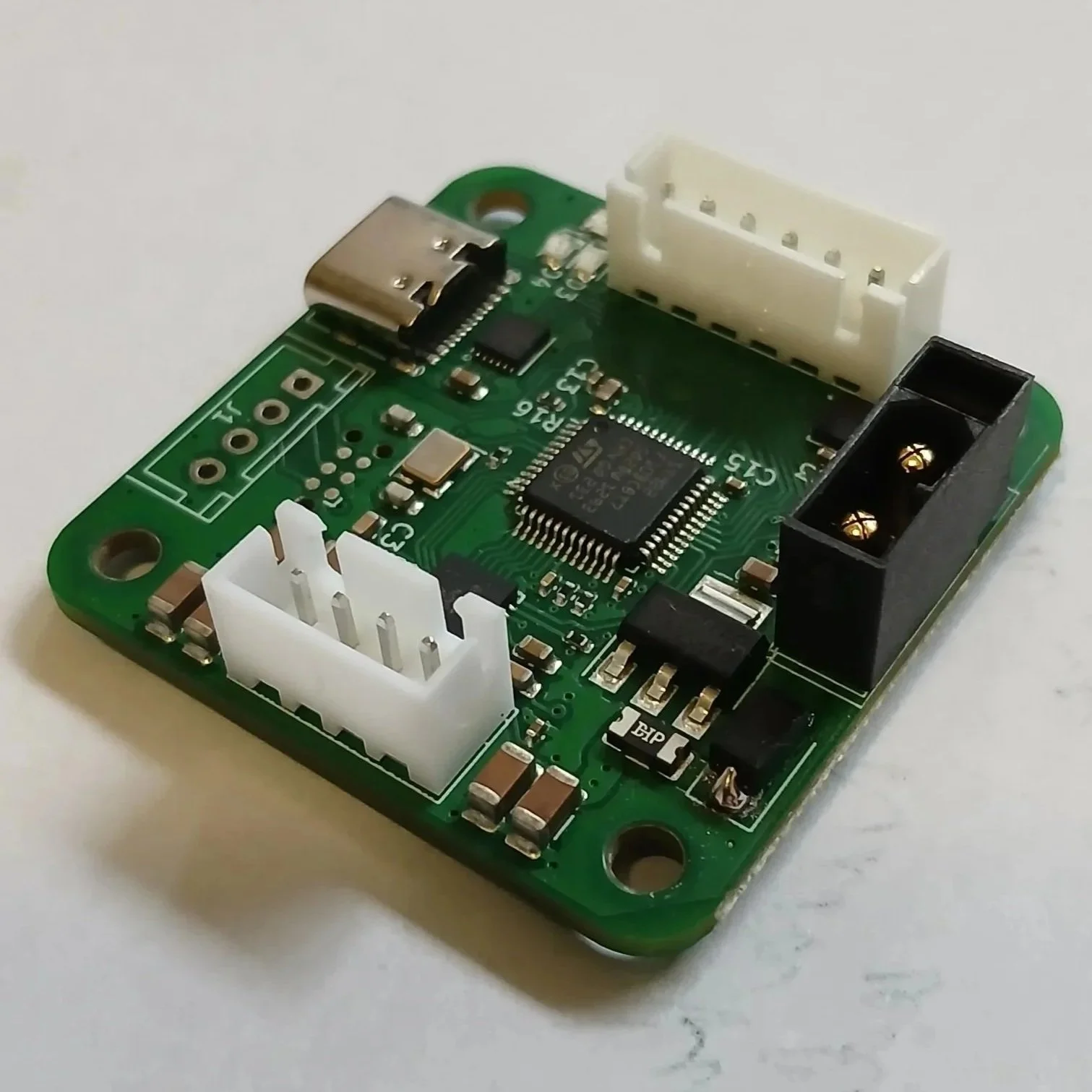
This project was more a "family" of boards, with the lessons taken from the last two motor controller projects i focused more on the exact use case i wanted for these designs, which was creating closed loop motor drivers (aka retrofitting all the Nema steppers i had lying about from harvested 3d printers i got from marketplace). This was also the first motor controller where i put serious effort into the firmware, first writing a bare metal implementation with usb-serial and can control options, then porting everything to a freeRTOS based system and implementing the CANopen protocol (much to the chagrin of the STMs flash and ram).
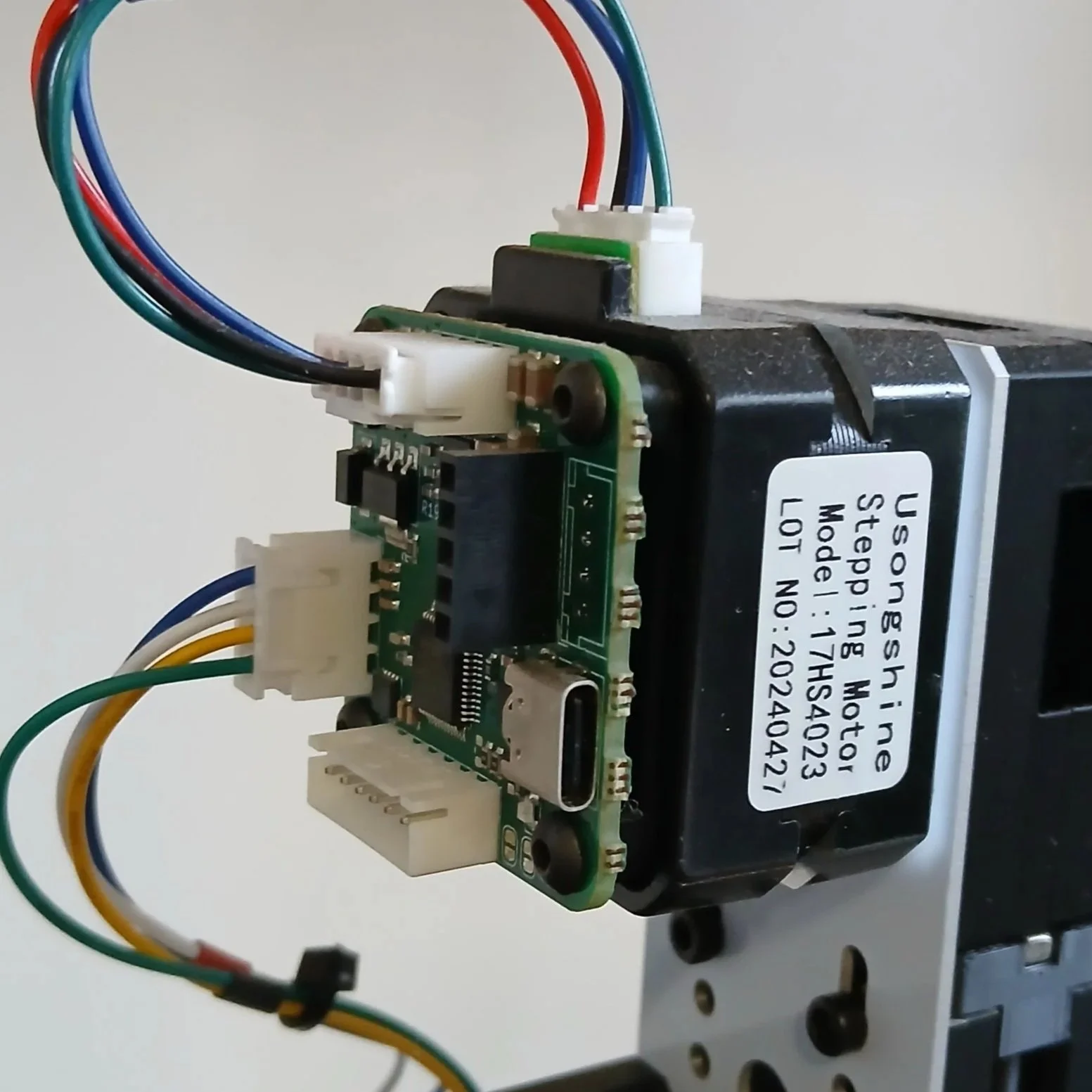
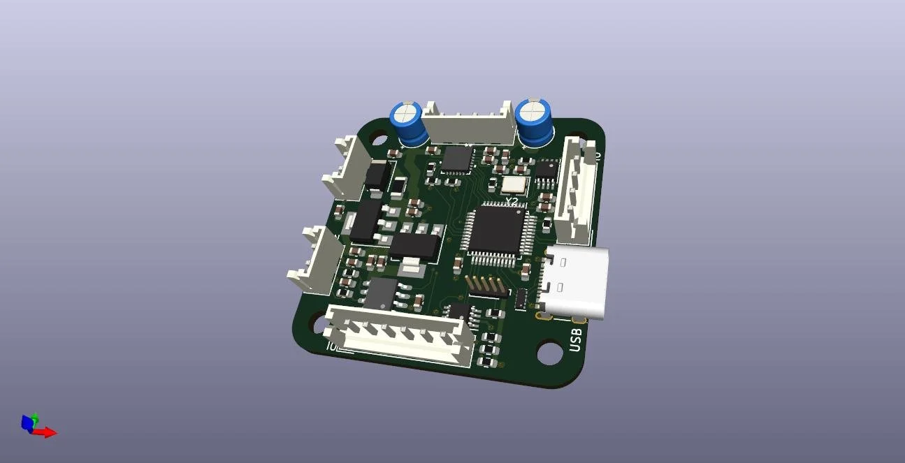
These boards all have a few things in common
-Mounting holes and formfactor to mount directly onto the back of a Nema14 sized motor
-AM5600 magnetic rotatory encoder chip mounted center on the underside of the pcb to align with a shaft mounted magnet
-USB-serial and CAN bus coms
-A few GPIOs broken out for use with limit switches or i2c devices
What makes them different?
-Some have a stepper motor driver while one has dual H-bridge driver
-Some have there current thresholds set by resistor dividers while others are more dynamic being controlled by PWM signal through a RC filter
-A few different connector typers were tried
-General refining and cramming in of featuers/extra optional GPIOs
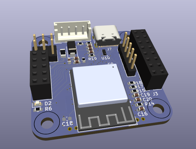
There was also one board version which used an ESP32S3 instead of the STM32 and didn't have a motor driver, the idea for this one was as a wifi to CAN bus link, thou i would later design other boards for this role.
Just as big a task as the hardware design for this project was the firmware. It was interesting trying to drive steppers with the dual H bridge version and gave me more appreciation for some of the intricoes of motor driving which you can gloss over when using dedicated driver chips (like decay modes, dynamic holding torque/current and how different micro stepping settings affect them). I started off with a bare metal implementation using interrupts and timers to handle the coms while keeping the control loop fairly tight (as well as handling the actual stepping pulses for the stepper versions), as well as my own primitive CAN protocol. The limits of this approach started to become obvious as the features crept in and while it was workable i eventually rewrote the whole thing using freeRTOS and CANopen which really pushed me to the limits of the RAM and flash on the STM32F103 but made keeping the code base understandable much easier. The firmware allows for the unit to be used as a open or closed loop stepper, can implement angular or speed closed loop control, can act as encoder piping data out of serial or CAN and has all the PID loop, min/max speed/angle etc settings settable and saveable to flash so it can handle power cycles. Nothing revolutionary to be sure but it was really rewarding to implement all the features i had no idea how to do when i made the first motor driver.