Motor Controller Madness
I’ve been interested in motor/servo controllers for a while now and this has led me to design a few of my own. These Designs were all mostly done as a learning experience and because I wanted to have a very “custom” motor control solution for a few mechatronic projects I was working on. All the boards below feature some similarities
They have a motor driver/s (for brushed or stepper motors or breakout PWM/GPIOs pins for other (maybe brushless in the future) which are controlled by an on board microcontroller
They have pins/buses broken out to allow feedback devices like rotary encoders (magnetic and quadratic) and limit switches to be attached and read by the microcontroller
They have communication channels (UART and CAN) to allow them to receive commands and send data to another systems
I call them Servo Controllers because when paired up with feedback sensors and a motor they turn the motor into a servo. Of course the exact software you run on them is what really defines their behaviour, and i have mostly been using them as positional servos.
Servo Controller Board V1
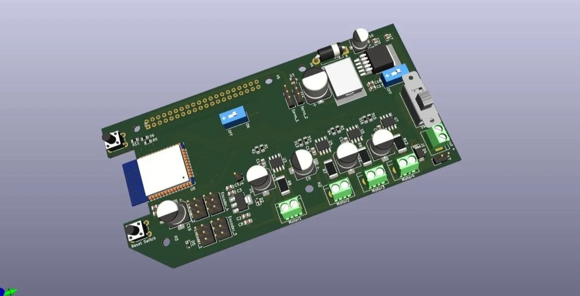
This design (V1) was built on the idea of being a raspberry pi shield. It would mount onto the back of a raspberry pis 40 pin header, some of its features included
Built in 5V Buck Converter to power both pi and motors from a single 12V supply
ESP32 microcontroller which handled generating the PWM signals for driving of the motors (DC brushed with a A4950E integrated H bridge) as well as connectors for I2C and SPI based magnetic encoders (also some endstops).
UART control interface so the pi (or anything else which could communicate via a standard UART port) could command the four motors
This board featured on the first iteration of my Emoji Bot
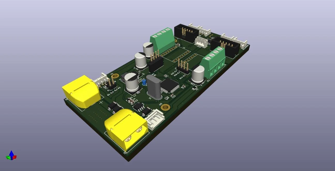
Servo Control Board V2
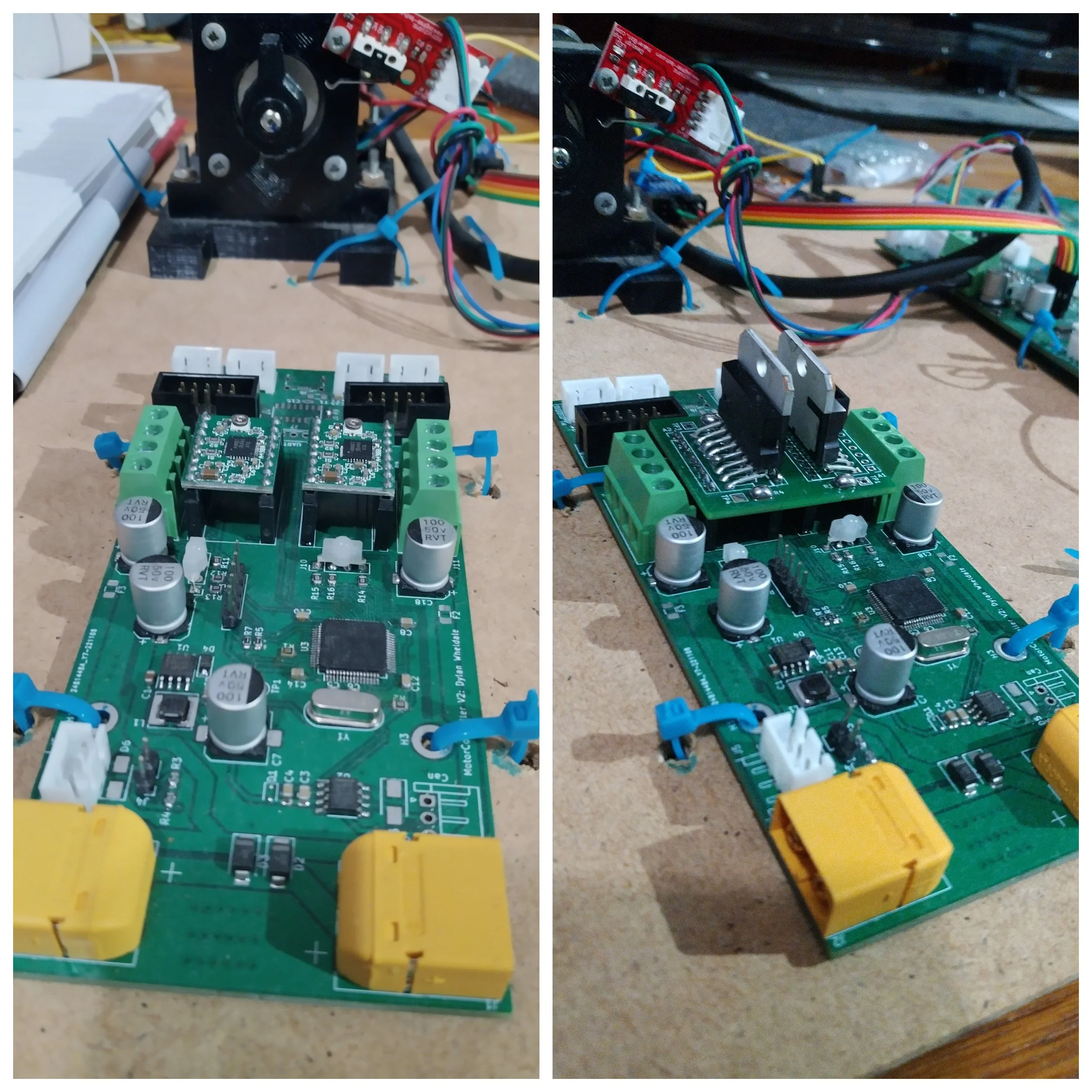
Servo Control Board V2 with different motor driver options
This design (V2) was more a learning exercise on the STM32 microcontroller line as well as an attempt to make a chainable motor controller which could have the “Motor driver” components swapped out to control different types of motors. Some of its features include
CAN bus and UART control interface
STM32 microcontroller with a number of connectors for I2C, SPI and quadrature based encoders as well as two “modular motor” connectors to place custom motor driver boards. These modular motor connectors had a number of pins (PWM capable and GPIOs) routed to them so different types of motor driver chips could be used. During testing i used a feature rich stepper motor drive chip (A4988) as well as a more basic Dual H-Bridge chip (L298N)
Servo Control Board V3
This next design was a move away from the more “general” purpose designs i had previously made and was more specific in that it was aimed purely for Nema 17 form factor stepper motors and was designed to be highly space optimized to make mounting easier. Its features
CAN bus and UART control interface
STM32 microcontroller with a number of connectors for I2C, SPI and quadrature encoders
2 I2C buses so as to enable the use of compound feedback loops which both utilize encoders which have hardcoded I2C addresses (AS5600)
Voltage selectable (5V/3V) quadrature encoder inputs
Rear mounted AS5600 magnetic encoder for mounting on the back of Nema 17 motors
Integrated DRV8425RGER Stepper motor driver
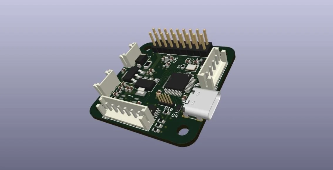
Expandable Servo Control Board (Based on Servo Control Board V3)
Above is a version of the V3 servo but without integrated stepper motor driver. A number of PWM and GPIO compatible pins (as well as 12V+ and GND) are broken out the the Pin headers allowing another board to be mounted there. This would allow me to use this board as a sort of CAN bus encoder OR a base for other random motor driver circuits.

Collection of Boards for mounting magnetic encoders
Above are a number of boards i used when experimenting with magnetic encoders from AMS, specifically the AS5600, AS5048A and AS5048B chips.
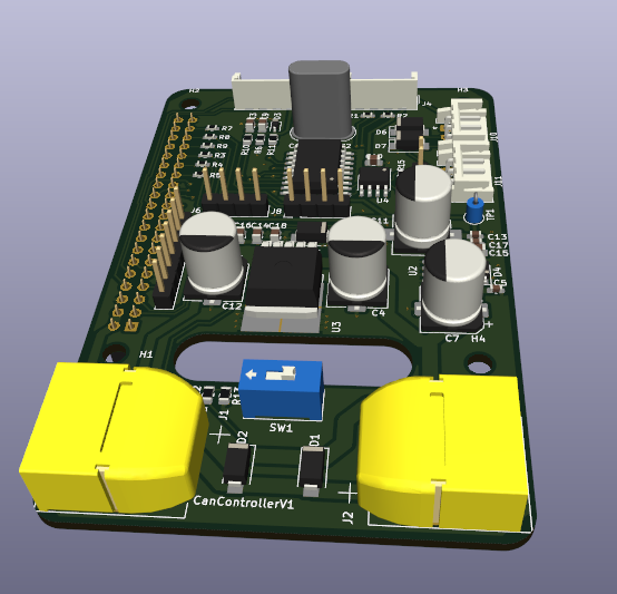
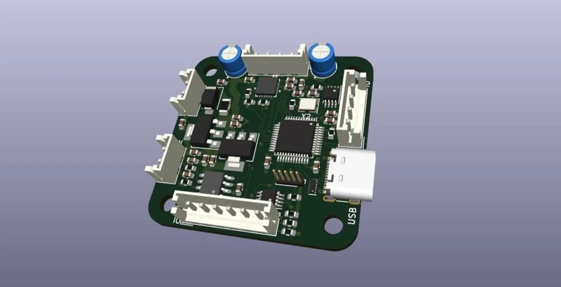
Can Control Board
Finally after initial testing i would need away to control the CAN capable boards, so i put together a raspberry pi Hat. This Hat features a 5V buck converter so the whole system of motors and Pi can be run from a single 12V source and it also features a SPI-CAN converter chip (MCP2515) because the raspberry pi dosn’t support CAN natively.